How to Size a Media Filter for a Specific Flow Rate
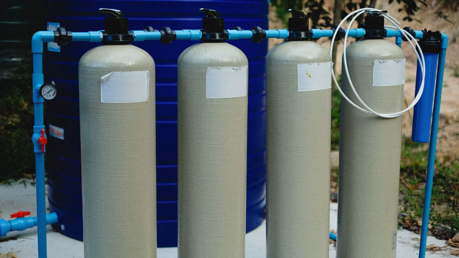
To size a media filter, determine required flow rate and select a filtration velocity. Calculate the filter area using the formula Area = Flow Rate / Velocity. Multiply by depth to find volume. Verify with a pressure drop check and safety margin.
- Filter sizing depends on the interplay between flow rate, filtration velocity, and bed depth.
- Use the formula Area = Flow Rate / Velocity to determine the minimum required cross-sectional surface.
- A 10 percent safety margin protects against clogging and ensures consistent water quality during peak loads.
- Always check the expected pressure drop across the bed to confirm the design meets pump capacity limits.
- Material compatibility and media size must be selected based on the specific source water characteristics.
Prerequisites for Accurate Sizing
Before calculating dimensions, you need three core data points. The first is the design flow rate, usually defined as the maximum throughput required during normal operation. The second is the target filtration velocity, which dictates how fast water moves through the granular media. The third is the desired bed depth, which determines the amount of media needed for adequate treatment performance.
Without these inputs, any sizing calculation is a guess. Engineers typically derive flow rate from the demand of the downstream process. For example, a boiler feedwater system might require a steady 50 cubic meters per hour, while a municipal pretreatment stage might handle a variable load peaking at 120 cubic meters per hour.
The filtration velocity is a design choice. It balances treatment efficiency against equipment footprint. A slower velocity gives water more time to pass through the media, improving particle removal but requiring a larger vessel. A faster velocity allows for a smaller footprint but increases the risk of channeling and early clogging. Common velocities for granular media filters range from 10 to 35 liters per minute per square meter, depending on the turbidity of the source water and the media type used.
Bed depth is the physical thickness of the granular bed inside the vessel. Shallow beds save space but offer less contact time. Deep beds provide more effective filtration but increase the weight of the vessel and the cost of media. Typical depths for sedimentation pre-filters might be 600 to 1200 millimeters.
Step 1: Define the Design Flow Rate
Start by identifying the maximum flow rate the filter must handle. This is the basis for the flow rate calculation. If the application has a stable demand, use the average flow. If the demand fluctuates, size the filter for the peak hourly demand to prevent the system from falling behind.
Consider the duration of the peak. A 30 minute surge might be handled by a slightly larger filter, while a year-round sustained load demands a larger vessel. Document the flow rate in cubic meters per hour or liters per minute. Consistency in units is critical to avoid calculation errors.
Step 2: Select the Filtration Velocity
Choose a filtration velocity based on the water quality and the required effluent standard. Lower velocities improve particle capture but increase the required surface area. Higher velocities reduce the footprint but may require more frequent backwashing.
Review the manufacturer data for the specific media. Coarse sand media can often handle higher velocities than fine sand or activated carbon. If the source water is highly turbid, err on the side of a lower velocity to protect the bed from rapid clogging.
Step 3: Calculate the Required Filter Area
Use the following formula to determine the minimum cross-sectional area of the filter:
Area = Flow Rate / Filtration Velocity
Ensure both values use compatible units. If flow rate is in cubic meters per hour and velocity is in liters per minute per square meter, convert the flow rate to liters per minute first.
Example Calculation:
If the design flow rate is 50 cubic meters per hour, convert this to 3,000 liters per minute.
If the selected velocity is 20 liters per minute per square meter, the required area is 3,000 / 20 = 150 square meters.
This result represents the theoretical minimum. It does not account for clogging, wear, or safety margins.
Step 4: Apply a Safety Margin
The calculated area is the bare minimum for the initial clean bed. Over time, the bed will clog, and the effective filtration area will decrease. To account for this, apply a safety margin.
A standard practice is to increase the calculated area by 10 to 20 percent. For applications with high variability or heavy solids load, a larger margin is prudent. In the example above, adding 10 percent gives a design area of 165 square meters.
This margin ensures the filter maintains performance even when the bed is partially loaded with captured solids. It also provides flexibility for future increases in flow rate.
Step 5: Determine the Vessel Dimensions
Convert the required area into physical vessel dimensions. For a cylindrical filter, the area is the cross-section of the circle.
Radius = Square Root (Area / Pi)
Using the 165 square meter example:
Radius = Square Root (165 / 3.14159) = Square Root (52.52) = 7.25 meters.
Diameter = 14.5 meters.
For a rectangular or box-type filter, divide the area by the chosen length to find the width. If the length is 20 meters, the width is 165 / 20 = 8.25 meters.
Round up to standard commercial sizes. Vessels are often built to specific diameters or widths to match standard plate-and-frame or welded shell specifications.
Step 6: Calculate the Media Volume
Once the vessel dimensions are set, calculate the volume of granular media required. Multiply the vessel area by the bed depth.
Volume = Area x Bed Depth
Using the cylindrical example with a bed depth of 1.2 meters:
Volume = 165 m2 x 1.2 m = 198 cubic meters.
This volume determines the cost of the media and the weight of the vessel when filled. It also dictates the number of media layers if multiple grades are used, such as a coarse layer on top and a fine layer below.
Step 7: Verify Pressure Drop
The final step is to verify the design against the expected pressure drop. As water passes through the granular bed, friction causes a loss of pressure. This pressure drop increases as the bed clogs.
A typical initial pressure drop for a clean bed is low. As the bed loads, it rises. The pump must be capable of overcoming the maximum anticipated pressure drop. If the calculated pressure drop exceeds the pump head, the filter is too small or the velocity is too high.
Check the pressure drop specification from the media supplier. If the data is unavailable, consult a hydraulic engineer to model the flow through the granular bed. This verification step catches sizing errors before the vessel is fabricated.
Common Sizing Mistakes
- Using the average flow rate instead of the peak flow rate. This results in an undersized filter that cannot handle surges.
- Ignoring the safety margin. The filter will clog too quickly, causing frequent backwashing and potential downtime.
- Selecting the wrong media size. A filter sized for fine media may clog rapidly if used with coarse media, or vice versa.
- Forgetting to account for the backwash cycle. During backwash, the filter is offline. The upstream storage must be sufficient to handle the water demand during this period.
- Neglecting the pump head. A well-sized filter that the pump cannot push water through is effectively useless.
Final Verification
Before ordering the vessel, perform a final review of the calculations. Re-check the unit conversions. Confirm the flow rate matches the process requirement. Validate the velocity selection against the media data.
Compare the final dimensions against the available installation space. Ensure the vessel weight, both empty and filled with water and media, is supported by the foundation. Verify that the inlet and outlet nozzles are sized correctly to prevent turbulence and short-circuiting.
Document all calculations in the design sheet. Include the flow rate, velocity, area, area with margin, dimensions, and media volume. This documentation serves as a reference for future maintenance and for troubleshooting if the filter does not perform as expected.
A correctly sized media filter operates efficiently and reliably. It delivers consistent water quality without excessive energy consumption. It avoids the costly issue of replacing an undersized unit or the operational headache of managing an oversized unit that wastes space and money.
The process is straightforward. Determine the flow. Choose the velocity. Calculate the area. Add a margin. Find the dimensions. Check the pressure. The result is a practical, functional piece of equipment tailored to the specific demands of the system.
Frequently asked questions
What is the standard filtration velocity for a granular media filter?
Typical velocities range from 10 to 35 liters per minute per square meter. The exact value depends on the media type and the turbidity of the source water.
How does bed depth affect filter sizing?
Bed depth does not change the required surface area, but it increases the total media volume and the weight of the vessel. Deeper beds provide better treatment but cost more.
Can I use a smaller filter if I backwash more often?
You can reduce the required area slightly by increasing the backwash frequency, but the filter will still need to handle the peak flow rate when it is not in backwash mode.
What happens if the flow rate exceeds the design capacity?
The filtration velocity will increase, leading to channeling, poor water quality, and rapid bed clogging. The filter will fail to meet the required effluent standard.
Is it better to oversize a media filter?
Oversizing increases the cost of the vessel and media. It can also lead to short-circuiting if the flow is not properly distributed. A properly sized filter with a safety margin is the optimal choice.